QUICK START GUIDE - Digital I/O for Raspberry Pi Starter Kit
Use your Raspberry Pi in the real world!
- Perfect for prototyping, proofs of concept, and
environments where an industrially hardened
controller isn’t required - Provides a reliable way to sense and switch industrial-level electrical loads with your own Raspberry Pi
- Includes Digital I/O Carrier Board, mounting rack, and four popular G4 I/O modules
- Code samples available at developer.opto22.com
Description:
The Digital I/O for Raspberry Pi Starter Kit gets you started sensing and switching industrial loads with your own Raspberry Pi.
The system includes the same field-tested, industrially hardened Opto 22 G4 input/output (I/O) modules used in automation applications worldwide for nearly 40 years. Just bring your Pi and its power supply, and you’re ready to begin.
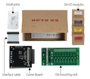
The Starter Kit is a $215 value for only $129 plus shipping. It includes all of the following:
• OPTO-P1-40P Digital I/O Carrier Board, including interface cable, Pi board mounting standoffs, and spare fuse for mounting rack
• G4PB8H 8-module mounting rack
• G4IAC5 90-140 VAC/VDC input module
• G4IDC5MA 10-32 VDC input module with manual/auto switch
• G4OAC5 12-140 VAC output module
• G4ODC5 5-60 VDC output module
With the Starter Kit, you can use your Pi to switch industrial-level electrical loads far beyond the Pi's built-in 3.3 VDC GPIO pins. You can monitor and control real-world devices like industrial motors, pumps, and sensors.
And you’ll know that you can count on reliable Opto 22 industrial I/O, manufactured and supported in the U.S.A. Product support is free, and most I/O modules are guaranteed for life.
GETTING STARTED
The Starter Kit works with any model Pi with a 40-pin header connector. Here’s what’s in the box:
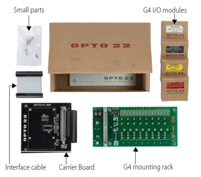
1. Snap the Carrier Board onto the G4 mounting rack connector.
2. Carefully open the bag of small parts.
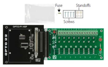
3. Use the four screws to secure the Pi to the top of the Carrier Board, placing a standoff between the Pi and the Board for each screw.
4. Insert one end of the interface cable into your Pi's GPIO connector. Insert the other end into the Carrier Board’s gray connector, making sure it locks in place.
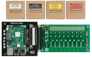
5. Remove an I/O module from its box and carefully install it in position 0 on the board. Secure it with its integral screw.
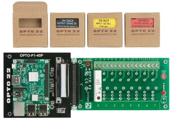
6. Install and secure the other 3 modules next to the first one.
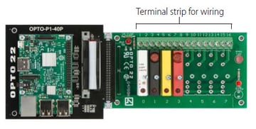
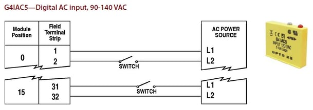
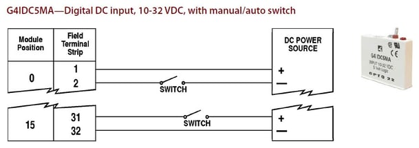
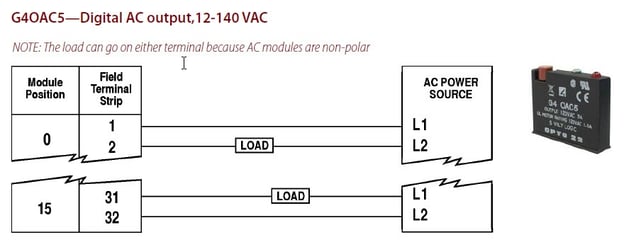
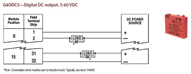
7. Follow Field Wiring Diagrams below to wire real-world sensors and devices to the mounting rack.
CAUTION: AC wiring is dangerous and should be done by a qualified electrician.
For additional wiring information and complete specifications, see the Digital I/O for Raspberry Pi Selection Guide. (This guide also shows all the other Opto 22 I/O modules you can use with your Pi.)
8. Plug in your Pi’s power supply.
9. Use your favorite Pi-supported programming language to read and write to the I/O points.
Visit developer.opto22.com for code samples and tips for using your Pi to read and write to Opto 22 I/O modules.
NOTE: Opto 22 I/O modules use negative true logic; that is, a zero bit means On and a 1 bit means Off. When reading and writing to I/O points, remember that 0 is On and 1 is Off.
Powering Peripherals
IMPORTANT: If your Pi uses USB-powered peripherals (especially hard drives or WiFi dongles), do the following:
• Connect a 5 V power supply rated 2.5 A to 5 A to the G4 rack’s power terminals (located underneath the Carrier Board).
• Replace the G4 rack’s standard 1 A fuse with the 5 A fuse that came in the bag of small parts. (If you need to replace this fuse, it is part number FUSE05B—10 pack.)
Mapping: GPIO Pins to G4 Modules
The diagram below will help you know which pins apply to each module on the rack.
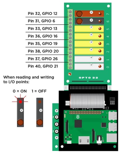
Mapping Overlay for Raspberry Pi
Place this overlay over your Pi's GPIO pins for a handy mapping reference. You can also download the template from developer.opto22.com.
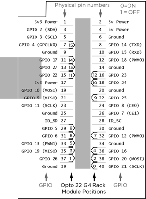
Field Wiring Diagrams
